

Venturi and orifice meters are both flow meters that apply Bernoulli’s principle to accurately measure flow, which can be difficult to directly measure especially in closed pipes.
This article will delve into the working principles of both venturi and orifice meters, discuss their differences and try to answer which is better for industrial application.
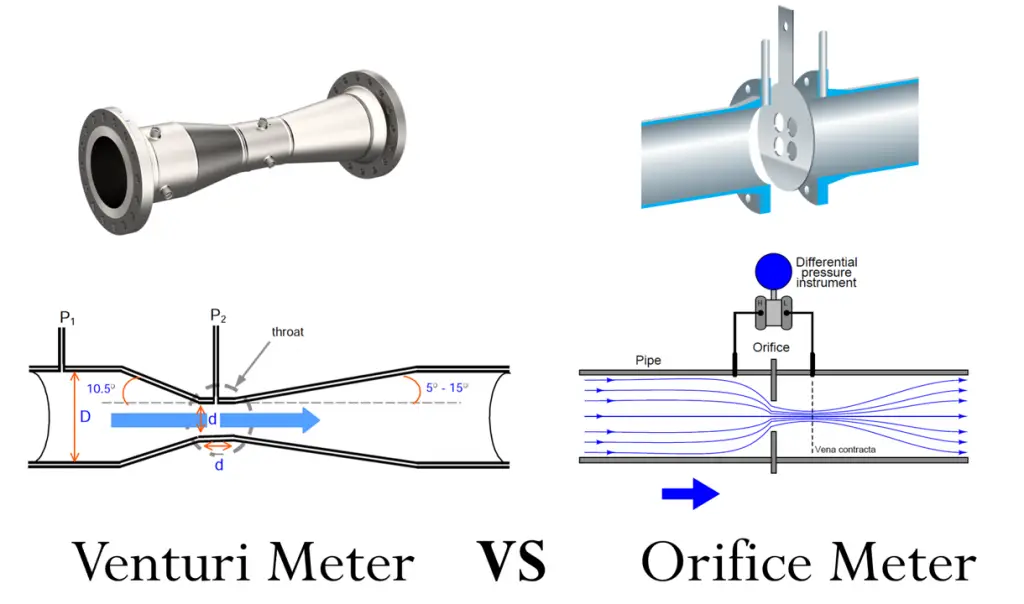
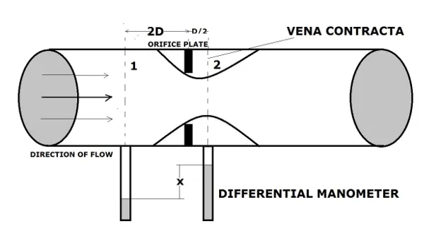
An orifice is a flat plate with a sharp-edged hole that’s inserted concentrically into the pipe to create flow restriction. When the fluid flows from the pipe to the orifice, fluid velocity increases. By Bernoulli’s principle, pressure decreases at the vena contracta (throttle area). As the cross-sectional area expands again, velocity decreases again back to normal.
The pressure points to be measured are at the inlet pipe to the vena contracta of the orifice.
A venturi meter has 4 parts — the inlet pipe, the converging section, the throat, and the diverging exit
Fluid flows from the pipe and its velocity gradually increases through the converging section with its peak velocity being at the throat. This is also where the pressure is at the lowest, but it’s regained as the fluid exits through the diverging section and goes back to the full pipe diameter.
The pressure points are measured between the inlet pipe and the throat.
The main difference between an orifice and venturi is in the structure. The venturi has a tapered structure which causes a gradual change in fluid velocity. Meanwhile, the orifice has a sudden change of fluid velocity because of the flat flanges.
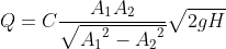
Both the orifice and venturi have the same purpose — to indirectly determine the fluid flow rate by measuring the pressure difference H between the inlet pressure and the throttle pressure.
Because of their structural differences but similar purpose, they are usually also compared side-by-side on the following criteria:
FLOW METER CHARACTERISTIC | VENTURI | ORIFICE |
| Pressure Loss | 2-3% in a well-proportioned pipe | 60-70% |
| Coefficient of Discharge | 0.984 – 0.995 | ~0.60 |
| Turndown Ratio | 10:01 | 3:1 to 5:1 |
| Cost | More expensive | Cheaper |
| Material | Stainless steel, cast iron, Monel metal or polyester glass fiber | Stainless steel, Monel metal, polyester glass fiber, brick and concrete (for larger pipes) |
| Fluid Suitability | Liquids with high solid content (e.g. slurry) & gas | Clean liquid & gas |
| Pipe Orientation | Horizontal, vertical, or inclined | Straight conduits, horizontal or vertical |
Pressure losses are irreversible mechanical energy loss due to other forces at play like friction. Some factors include the turbulence of the fluid, fluid viscosity, pipe material and structure, or pipe fittings. Ideally, a smooth straight conduit at laminar flow with zero working parts will have the least pressure loss.
Because of the venturi’s tapered structure, the pressure loss is lesser than that of the orifice. In the orifice, the upstream inlet pressure is not fully recovered past the vena contracta because of the friction at the sudden contraction around the flanges.
The coefficient of discharge, C, is a ratio between the actual discharge to the ideal discharge (when there are no head losses). The C values, determined through experiment, are a function of Reynold’s Number. The graphs below show how C varies with the fluid flow.
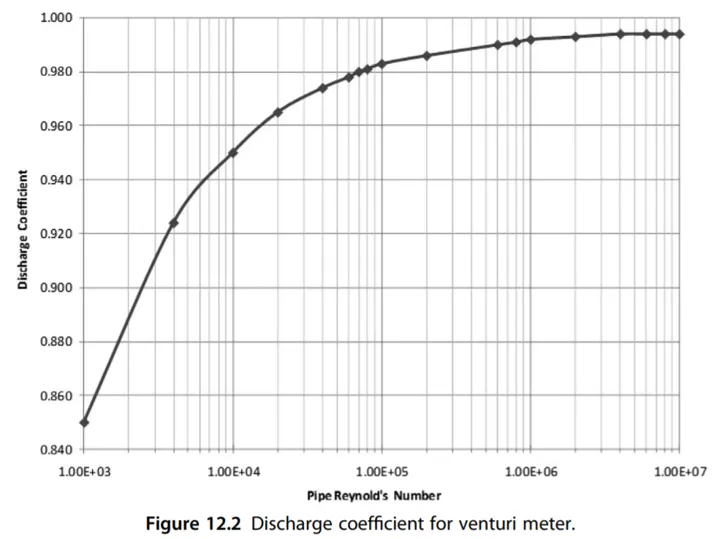
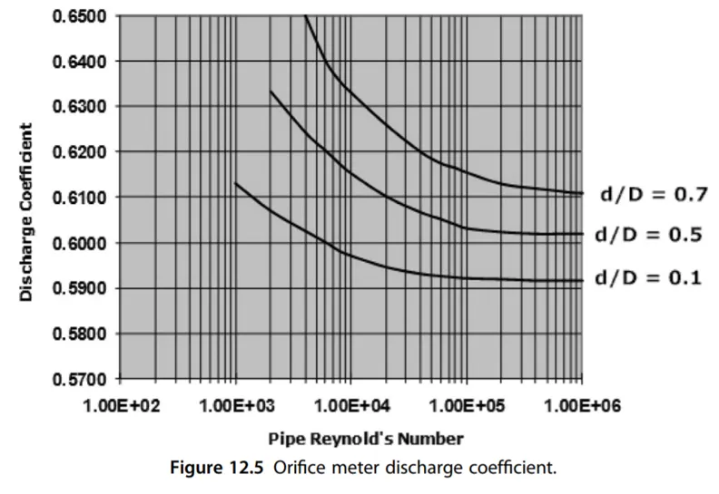
Since orifice has greater pressure loss than venturi, its coefficient of discharge is also lower. For the venturi, it increases when it is machined for a smoother surface.
It is the ratio of the maximum to minimum flow capacity. Design manufacturers look into this parameter because it describes the rangeability of a flow meter. For example, if your feed inlet is pre-determined to run between 100,000 to 300,000 m3/day, then you’ll have to find a turndown ratio of at least 3:1.
Venturi meters are more expensive to install. To create a tapered pipe, there must be ample space before and after the throttle area. They are constructed permanently into the pipe in stainless steel, cast iron, Monel metal, or polyester glass fiber.
Meanwhile, the orifice is simpler to install and much cheaper because you simply insert the orifice plate concentrically. It can be made from stainless steel, Monel metal, and polyester glass fiber. For larger pipes like those used in the sewers, brick and concrete material is more suitable.
Venturi meters are more suitable for fluids with high solid content because it has lesser clogging tendencies. Orifice, on the other hand, has dead zones in the areas surrounding the flange so it’s more suitable for clean fluids.
Orifice meters can be applied to straight conduits only — horizontal or vertical. Venturi meters are more flexible — horizontal, vertical, and inclined.
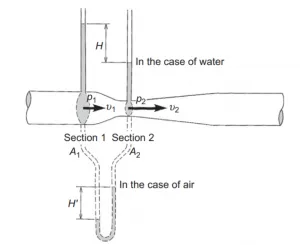
Both venturi and orifice flow meters measure the static pressure between 2 points using a manometer, denoted as H.
From Bernoulli’s equation and using the continuity equation, the volumetric flow rate Q is calculated as:
Where
Only the H parameter will be measured directly using a pressure gauge such as a manometer. The values for C and A2, however, will vary depending on the type of flow meter used. Let’s look into 2 types of flow meters — orifice and venturi.
Fluid flows from the pipe and its velocity gradually increases through the converging section with its peak velocity being at the throat. This is also where the pressure is at the lowest, but it’s regained as the fluid exits through the diverging section and goes back to the full pipe diameter.
The pressure points are measured between the inlet pipe and the throat.
Venturi meters are considered more accurate and a much better choice because:
Venturi meters are used in petroleum industries where operating conditions are extreme, or in wastewater industries because of the fluid’s high solid content.
The only major downside to venturi meters are their expensive installation costs. If you opt for a cheaper alternative, the orifice meter will also work. However, you may incur more expenses with maintenance and operating costs.
Boucher, R. F., & Nakayama, Y. (1999). Introduction to Fluid Mechanics (R. F. Boucher, Ed.). Elsevier Science. 10.1016/B978-0-08-102437-9.00005-X
Chivers, P. J., & Bird, J. O. (1993). Newnes Engineering and Physical Science Pocket Book. Newnes. 10.1016/B978-0-7506-1683-6.50052-7
Dryden, I. G. C. (Ed.). (1982). The Efficient Use of Energy. Butterworth Scientific in collaboration with the Institute of Energy acting. 10.1016/B978-0-408-01250-8.50027-1
Flowmeters – Turndown Ratios. (n.d.). The Engineering ToolBox. Retrieved March 3, 2022, from www.engineeringtoolbox.com
Menon, E. S. (2015). Transmission Pipeline Calculations and Simulations Manual. Elsevier Science. 10.1016/b978-1-85617-830-3.00012-2
Venturi Tube Questions & Answers. (n.d.). Armstrong International |. Retrieved March 2, 2022, from www.armstronginternational.com
")